


Design for Manufacture and Assembly (DFMA®)
Product Costing and Simplification
Balancing the objectives of cost, time, function and quality
| There is a project management saying about cost, time and quality; pick any two of the three. On top of that, the product must also function in a manner consistent with the expectations of consumers. But what if there was a way you could balance each of these goals? Using a question and answer approach, DFMA software tools allow you to achieve cost reduction and quality improvement in a short amount of time. The consumer receives the product they desire at a lower cost to the producer. From the earliest conceptual stages of |
 |
product development, to the purchase of parts from your supply chain, DFMA provides a way to work creatively and objectively to find new avenues for improving profit margins.
Why do DFMA®
Promote a fuller understanding of manufacturing, assembly, service and environment issues in design stage
Encourage multi-discipline participation
Provide a structured procedure for new product development
Provide more information than traditionally available
Promote and encourage Teamwork
Why Teamwork?
More effective responses to unexpected changes in product requirements
Empowers collective ownership of the design
Moves problem-solving periods to design’s concept stage
Eliminates the resistance to change encountered with individual ownership
Cultivates a ‘right-first-time’ approach...
Why Is DFMA So Important?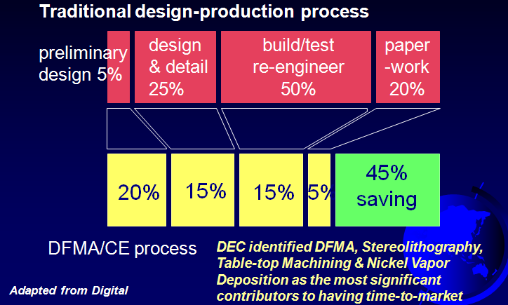
DFMA Software Products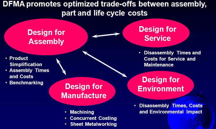
Who Casts the Biggest Shadow? 
The DFMA Product Design Process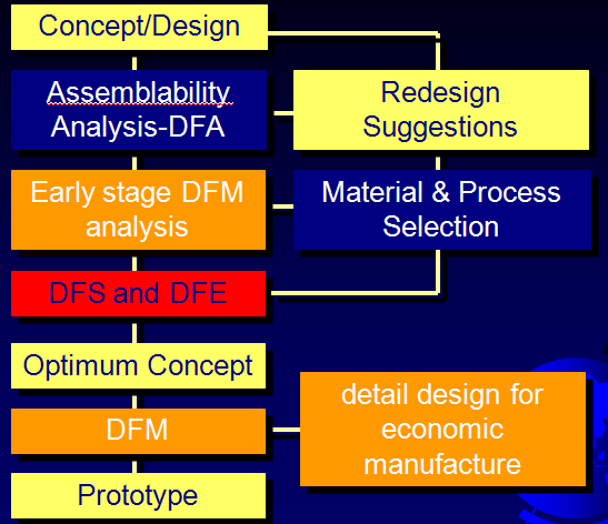
How the DFMA approach differs...
Cost of Change
According to President Hiroshi Hamada of Ricoh, they did not detect a problem with one of their Copier designs until after the product was shipped to customers. The real cost was $590,000!
Had the problem been corrected earlier, the cost would have been:
during design: $35
before purchasing: $177
before production: $368
What is DFMA?
DFMA® (Design for Manufacture and Assembly): Software that uses a question-and-answer approach to help determine the most cost-effective and efficient materials, manufacturing process, and assembly method for a particular part or product.
Engineers employ Design for Manufacture software to obtain early cost estimates on a particular part or product, using the world’s most comprehensive database of processes, materials, and machinery. DFM software gives engineers tools for deciding where cost is necessary in a design—and where cost can be removed—without compromising product function.
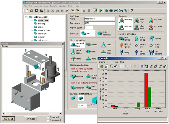
Product design and manufacturing engineers use Design for Assembly software to analyze the various methods that could be used to manufacture a product. Using this tool, the design is simplified repeatedly until the assembly process is as streamlined as possible and the part count has reached a cost effective minimum.
Top companies use DFMA to achieve three main goals:
1. Improve their products while reducing cost. They simplify their products, improve quality, reduce manufacturing and assembly costs, and quantify improvements.
2. Increase competitive advantage. They study competitive products, determine quality and quantify manufacturing and assembly difficulties, and create superior products.
3. Hold suppliers accountable. They use DFMA as a “should-cost” tool to predict costs, analyze and discuss supplier bids, and hold outside suppliers to best practices.

Here’s an example of an assembly simplification process using DFMA. The product starts out easy to design but difficult to assemble. The engineer focuses on reducing parts, integrating parts, and simplifying assembly. The end result is a more sophisticated design that is much easier to assemble. The cost is reduced by 42% and the assembly time is cut by 58%.
Analysis of hundreds of DFMA case studies reveal, on average, a 42% reduction in labor costs, a 54% reduction in parts, a 60% reduction in assembly time, a 45% reduction in product development cycles, and a 50% reduction in cost.
In Summary, what does DFMA give you?
Provides a structured approach
- to concept design evaluation & measurement
Identifies Minimum Number of Parts
- Criteria that questions the need for each item
Highlights Process Difficulties
- that cause cost & quality penalties
Estimates Process Time & Cost
- quantifies the size of problems, provides data for part, tool, & process
Comparative Indices
- measures ‘actual’ against ‘ideal’, -to ‘grade’ concepts
DFMA SOFTWARE PRODUCTS
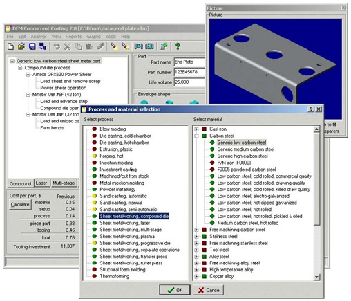
DFM Concurrent Costing software allows you to quickly estimate the cost of manufacturing your product, and provides an easy method for comparing “what-if” analysis for alternative manufacturing processes and material selection.
Click here for more info on DFM software
DFA Product Simplification software is used to reduce the complexity of a product by consolidating parts into elegant and multifunctional designs resulting in significant cost savings.
Click here for more info on DFA software

DFMA Software Average Reductions
| Labor Costs | 42% |
| Part Count | 54% |
| Separate Fasteners | 57% |
| Weight | 22% |
| Assembly Time | 60% |
| Assembly Cost | 45% |
| Assembly Tools | 73% |
| Assembly Operations | 53% |
| Product Development Cycle | 45% |
| Total Cost | 50% |
| Results compiled from over 100 published case studies |
2) DFM(Design for Manufacture)
Vital to Manufacturing Competitiveness
Design for Manufacture is a systematic approach that allows engineers to anticipate manufacturing costs early in the design process, even when only rough geometries are available on the product being developed.
Given the large number of process technologies and materials available, few design engineers have detailed knowledge of all the major shape-forming processes. Consequently, engineers tend to design for manufacturing processes with which they are familiar. DFM methodology encourages individual engineers and concurrent development teams to investigate additional processes and materials and to develop designs that may be more economical to produce. With more information about viable processes and materials, users can quantify manufacturing costs for competing design alternatives and decide which design is best.
Design for Manufacture provides guidance in the selection of materials and processes and generates piece part and tooling cost estimates at any stage of product design. DFM is a critical component of the DFMA process that provides manufacturing knowledge into the cost reduction analysis of Design for Assembly.
DFM Concurrent Costing is a software tool to generate cost estimates for both piece part cost and tooling investments. Unlike existing parametric cost estimating models, DFM Concurrent Costing does not rely on historical data and therefore allows you to generate accurate cost estimates for new designs and explore alternative materials and processes.
Benefits of using DFM Concurrent Costing software
A Highly Accurate Cost-Estimator
Gain quick insight into the tremendous cost impact of even simple changes to part dimensions. DFM Concurrent Costing provides a fast, accurate way to review evolving designs for cost efficiency by quickly simulating the use of alternate materials and comparing various shape-forming processes.
An Aid to Concurrent Engineering
Shorten product development cycles by working collaboratively on cost decisions. Because DFM Concurrent Costing is so easy to use, designers and manufacturing engineers can work closely with personnel from marketing, finance and purchasing to analyze alternative materials and process options.
A Useful Design Tool
Redesign existing products for better quality and manufacturability while still adhering to manufacturing cost requirements. DFM Concurrent Costing effectively aids redesign by offering quick testing of alternate materials and processes.
An Effective Vendor-Negotiating Aid
Evaluate vendor quotes by comparing the information the software provides on such items as total cost, cycle time, machine size and die cost. DFM Concurrent Costing gives even nonspecialists a foundation for meaningful discussions with vendors.
A Competitive Benchmarking Tool
Compare your designs with competitors’ products to determine market feasibility and to target costs. Because of its accuracy in predicting costs, DFM Concurrent Costing adds advantage to companies seeking to enter competitive industries.
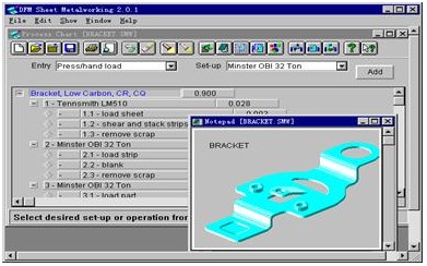 DFM Sheet Metalworking
3)DFE(Design for Environment)
Meeting the needs of an increasingly eco-conscious marketplace, DFMA allows product designers to conduct an environmental assessment during the concept stage of design, where they can evaluate the impact of material selection as well as account for the end-of-life status of their product.
The analysis prompts designers to select from the DFMA database the materials they prefer to use or avoid, then reveals the proportions (by weight) of those materials in the product. It also estimates and designates the proportions of product that go to different end-of-life destinations, including reuse, recycling, landfill and incineration. These measures help manufacturers meet such requirements as the European Union’s Restriction of Hazardous Substances (RoHS) regulations.
Q & A about Design for Environment
How does adding a Design for Environment capability to the Boothroyd Dewhurst, Inc., Design for Manufacture and Assembly (DFMA™) software help manufacturers achieve “green” or “sustainable” programs for their products?
This new DFE capability identifies and rates materials for their compliance to changing standards regarding toxicity and end-of-life destinations. Our motivation for adding this software enhancement largely comes from introduction of such EU legislation as the Waste from Electronic and Electrical Equipment (WEEE) directive and the Motor Vehicles directive. Manufacturers must demonstrate that their new products don’t contain certain banned materials—Restriction of Hazardous Substances (RoHS) compliance—and that a certain proportion of the product is reusable or recyclable at end-of-life.
DFMA software can be deployed at the earliest stages of product development when designs are often just rudimentary geometries without detailed computer-aided design (CAD) features. This is often the easiest and certainly the most effective stage for manufacturers to address the issue of DFE material selection.
Integrated DFMA/DFE analysis provides design and manufacturing cost savings, warns design teams about materials to avoid, and documents environmental compliance.
How does the DFE capability in the DFMA software differ from sustainability efforts already underway in product engineering companies?
DFMA supports sustainability initiatives by raising awareness of recycling and remanufacturing options at the design level. The software currently does not include additional life-cycle analysis (LCA) costs or assessment of disassembly effectiveness.
DFMA product simplification with DFE capability helps compress greater performance into fewer parts—guiding design engineers to use the most sustainable and cost-effective materials and manufacturing processes. DFMA product evaluation opens numerous doors to sustainable, innovative design.
What information is in the DFE portion of DFMA?
The DFE portion is integrated with the materials library of the DFM Concurrent Costing database of DFMA. This library gives designers a comprehensive understanding of the costs to manufacture parts by means of turret pressworking, laser and plasma cutting, sheet metal stamping with a variety of dies, machining, structural foam molding, plastic extrusion, injection molding, thermoforming, blow molding, cold and hot die casting, hot forging, powder metal processing, sand casting, investment casting and metal injection molding.
Existing DFMA data for each individual material associated with the above shape-forming processes has been expanded to include DFE information. Materials in the software are now classified for the designer as ferrous metals, non-ferrous metals and other, and they are categorized as “preferred,” “non-preferred” and “avoid.” The “avoid” category will include materials on the EPA banned substances list, and─for European software─materials that will prevent RoHS compliance. The software estimates and designates the proportions of product that go to different end-of-life destinations, including reuse, recycling, landfill and incineration.
During DFE analysis, items in the product that are designated to be recycled, and that include mixed materials, are understood to be processed by bulk recycling. During bulk recycling, items are shredded; the resulting material mix is separated by magnetic and eddy current separation. The software assumes that ferrous and non-ferrous metals can be readily separated from the shredded-materials mix, while other materials cannot. Some stainless steels, although ferrous-based, are non-magnetic and consequently are designated “non-ferrous.”
Manufacturers can easily add their own preferred DFE materials to the DFMA database, or just to the specific project analysis they have underway in the software.
Who is the primary user of the DFMA-plus-DFE analysis and why?
The new DFE capability has been developed for easy use by the design engineer at his or her work station. No life-cycle data is currently generated by the software, so an LCA expert is not required at this level. Some input on the recyclability of various materials may be needed, depending on the specialization of the manufacturer.
The goal is to allow product development teams to make quick, basic decisions about environmental impact issues early in the process of defining products. This approach recognizes the challenges design engineers face integrating numerous product requirements, and it promotes the creation of “greener” products.
What does Boothroyd Dewhurst, Inc. bring to the field of DFE analysis?
Boothroyd Dewhurst has been in the Design for Environment (DFE) business for 15 years. Its development team has worked extensively with major manufacturers and researchers toward a fuller understanding of the role that product design and manufacturing can play in reducing negative environmental impacts.
DFE is not a start-up effort for the company. Depending on the readiness of the market to implement meaningful environmental programs, Boothroyd Dewhurst, Inc. will consider launching software upgrades based on its years of research in product disassembly methods and cost and end-of-life analysis.
The company’s particular expertise is in bringing environmental knowledge into the product design process very early, starting at the conceptual stage with raw shapes and continuing through the feature-building, advanced-costing stages of product design. This is what currently distinguishes DFMA 2009 from CAD/CAE/PLM product design tools that offer environmental compliance checks of Bill-of-Materials (BOM), or help create environmentally friendlier designs by targeting weight and material optimization. Such efforts generally take place after CAD models are extensively detailed. Likewise, proprietary internal LCA expert programs at leading manufacturers are often deployed as add-on requirements for the designer, usually after work on a BOM has already begun.
Boothroyd Dewhurst, Inc. feels that both environmental and product cost decisions need to be made together as early as the conceptual design stage.
For more information about DFMA, please click here.

Design For Assembly In Action
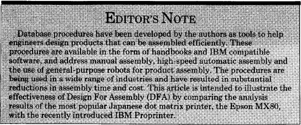
BDI Professors P. Dewhurst & G. Boothroyd,University of Rhode Island
A striking comparison of two different product designs, the Epson MX80 and IBM Proprinter,highlight the importance of the Design for Assembly approach.
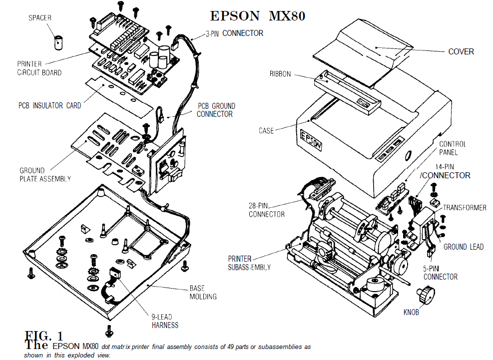
The Epson MX80
An Epson MX80 dot matrix printer was disassembled and analyzed for manual assembly using DFA procedures.
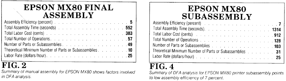
As a first step, the final assembly only was considered as shown in the exploded view, Fig. 1. A summary of this analysis is shown in Fig. 2. The final assembly involves 57 separate assembly operations and takes an estimated total assembly time of 552 seconds.Moreover, of the 49 different parts or subassemblies added in the final assembly process only 10 satisfy the criteria for separate parts’. This gives rise to a very low efficiency of only 5% and indicates great potential for part count reduction. The low assembly efficiency is also due to the fact that many of the parts are difficult to align and locate and require repositioning for insertion of fasteners. A breakdown of the total assembly time of 552
seconds is as follows:
As is common in most mechanical product designs, fasteners outnumber the functional parts in the product and represent a major portion of the assem-bly time. Clearly, eliminating fasteners in favor of an integral fastening design constitutes the greatest potential for reducing part count and assembly time.However, the three separate printed circuit boards, spacers, insulators and connectors offer further significant possibilities for design simplification.
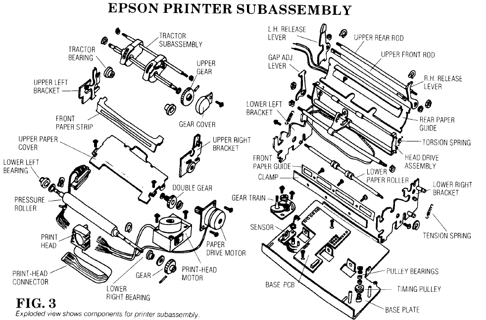
The final assembly of the Epson MX80 involves positioning and securing the main printer subassembly which includes the paper and print-head drive units. The second step in the design analysis involves the main printer subassembly, shown in the exploded view, Fig. 3. The essential design features of this subassembly are a stamped steel baseplate and two steel lower side brackets that are assembled into slots in the base. A cover is secured across the top of the side brackets,and this in turn supports two upper side brackets. Steel rods also stiffen the entire assembly. The main difficulty with this design is that almost all of thefunctional parts either hang between or on the outside of the side brackets. Most of the parts remain unsecured untit the upper front and rear rods are in place and the hexagon nuts are secured against the upper and lower bracket sides.
Good Design For Assembly practice requires the exact opposite of this approach. That is, parts should be added in layer fashion from the base plate and should either be self-locating or secured immediately. In the Epson MX80 design, the base plate supports only a printed circuit board and the printhead belt drive mechanism. The side plates, which are only loosely held in place are required to support all other parts until final securing takes place with hex nuts.
A summary of the DFA analysis for the printer subassembly is shown in Fig. 4. It can be seen that 128 separate operations are involved taking an estimated time of 1314 seconds and giving an assembly efficiency of only 7%. As with the final assembly, a central problem with the design is the large number
of fasteners. A breakdown of assembly time is as follows:
As was the case in the final assembly process, many operations in the main subassembly involve difficult alignments,adjustments, and obstructed access for insertion of both parts and fasteners. The MX80 has a reputation for high quality and reliability, but it is clear that it does not stem directly from the design but must result from skilled and careful assembly work.
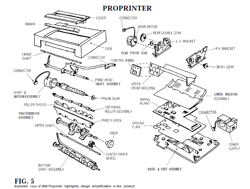
The IBM Proprinter
Recently the new dot matrix printer called the Proprinter was announced by IBM. It is a replacement for the Epson MX80 printer which has been marketed by IBM under their name and supplied with the PC and XT range of computers. The authors understand that this new printer was designed specifically with robotic assembly in mind, and is a design that involves several revolutionary concepts and avoids the use of screws or other separate fasteners. The final assembly of the Proprinter is being done at IBM’s Information Products Division, Charlotte, N.C.
It should be made clear that the authors had no specific knowledge of the labor rates, machinery costs or production parameters appropriate to this particular assembly plant location. Also, it should be understood that any conclusions drawn in the study reported here are subject to the assumptions made regarding these values.
Figure 5 shows an exploded view of the Proprinter with reasonably descriptive names given by the authors to the various parts and subassemblies. In all, there are 32 parts if the four connectors that must be inserted into the printed circuit board are considered separately. The Proprinter is a remarkable design in that all parts or subassemblies snap together during final assembly without the use of fasteners. Even the two motors and the heavy power supply snap into place with fairly simple double motions. It is evident from even a cursory inspection that this is an excellent design for manual assembly. However, its suitability for robot assembly requires more careful analysis.
Before looking at the results of the assembly analysis, the validity of the assumptions regarding labor and equipment costs and production parameters should be considered. Cost and Parameter Assumptions: Figure6 presents the values of the important basic costs and parameters used throughout the analysis. These values were deliberately biased in favor of robot assembly. For example, the cost of $50,000 per year, including overhead, for one assembly operator is quite high-a figure of $30,000 is more usual. The cost of one Scara-type robot arm with controls, gripper and sensors of $60,000 is relatively low.
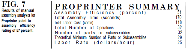
The assumption of two shifts working also helps justify automation equipment. Manual Assembly Analysis: In any Design For Assembly study it probably is worthwhile to perform an analysis for manual assembly first in order to provide a benchmark for subsequent comparisons. Figure 7 presents a summary of the analysis for manual assembly. The total assembly time is 170 seconds and with a labor rate of $50,000 per yeae($25/hr), this gives a total manual assembly cost of 118 cents per unit.
As each part is considered in the design analysis, an evaluation must be made as to whether or not it qualifies as a separate are candidates for being eliminated through product redesign; namely, the three connectors. Theoreti-cally, these connectors could be inte-grated into the assembly to which they are connected by the res[ective leads. This not only would eliminate the leads.This not only would elimiate the leads but would also allow the electrical con-nections to be made when the parent assembly is inserted. With this design about 12 seconds of manual asembly time could be saved .for a part that is easy to grasp,manipulate and insert with one simple motion,a total assembly time of about three seconds is appropriate.if the 29 parts were all this easy to assemble,then the total assembly time would be 87 seconds.comparing this figure with the estimated assembly time gives an assembly efficiency of 51%,meaning that the possibility exists for further improvement in assemblability.However,this figure takes no account of practical limitations and,in fact,represents an outstanding achievement.Assembly efficiency figures of less than 10% are more common for this type of porduct--recall the 5% and 7% values for the epson printer.
Robot Assembly Analysis
Turning now to robot assembly analysis it should be realized at the outset that this is camied out for three different typers of assembly systems: single-station with one robot arm,single-station with two robot arms and the multi-station robot system.After entering data into the Design for Robot Assembly Program the summary of results as shown in Fig 8 was obtained for the multi-station system.
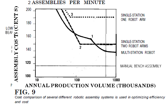
Figure 9 shows how total assembly costs vary for each robotic system and with different production volumes.For a single-station one-arm system the assembly time was estimated to be 211 second,representing an annual production volume of 68,000 units.The corresponding assembly cost is 190 cents (point 3 on the graph).
For higher prooduction volumes multple systems result in the same assembly cost.However,lower production volumes obtained by under utilization of one system result in rapidly increasing costsdue to the special-purpose equipment that cannot be used for other products.Similarly one single-station two-armsystem requires 101 seconds to complete the
assembly (143,000 per year) at a cost of 150 cents. This condition is point 2 on the graph.
Because multi-station machines can be configured in a variety of ways, they can be designed to match the required production volume. The condition marked point 1 represents the smallest practical multi-station machine fully utilized. This situation results in production of about one assembly per minute, or 240,000 units per year. However, for the Proprinter, a system with only one more station results in the production of two per minute and 480,000 units per year at a significantly lower cost of 136 cents. It was this latter condition that was selected as being the most favorable for robot assembly.
A major problem when considering assembly of the Proprinter using singlestation systems is the number of special tools and grippers required. This not only increases the cost of the equipment but lengthens the assembly cycle time due to frequent gripper changes. With the one-arm system about one third of the cost of the total system is attributable to special robot tools. Many of the parts are difficult to grasp and could have been provided with design features that facilitate gripping. However, with the multi-station machine this is a relatively minor problem because the various robots can be provided with suitable grippers for the work at that particular station and the need for gripper changing is avoided. In the case of a one-arm singlestation system approximately one half of the cycle time in assembling the Proprinter would be spent on gripper changing.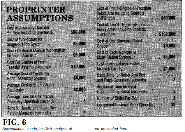
Another problem highlighted in the analysis is that the majority of parts involve multiple insertion motions requiring a more expensive robot than the simple four-degree-of-freedom Scara type. Of course in a single-station system, even if only one part requires a multiple motion (insertion path), the more expensive robot will be required. On a multi-station machine, different robots can be employed at each station. However, all of the five robot stations proposed in this analysis require the more expensive six-degree-of-freedom robot arms. Further consideration probably could have been given to assembly from one direction in the Proprinter.
It should be noted that the design for assembly software assigns a relative cost factor for the robot arm required for each assembly operation depending upon the difficulty of the task. This cost factor is then multiplied by the cost of a four-degree-of-freedom robot arm which is one of the basic costs in the user interactive data base, see Fig. 6. In this way the appropriate arm cost is identified for a single station system or for each station on a robot assembly line. 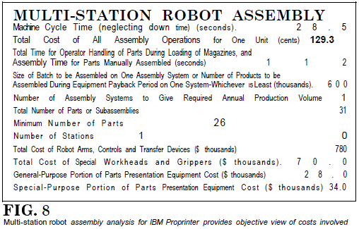
A significant aspect of this analysis is the time estimated for manually loading the various parts or subassemblies into pallets or magazines for presentation to the robot. Very few parts can be fed and oriented automatically, and an allowance has been made for manual loading time and pallet cost. Regardless of the assembly system used, the total manual time is estimated at 119 seconds; this figure includes 28 seconds for manual assembly of the flexible roller shield and the four flexible connectors. The individual times for manual loading were obtained from the results of the manual assembly analysis by adding the manual handling time to the time of 1.5 seconds for an easy insertion operation. This gives a total time of 91 seconds, representing a cost of 63 cents per assembly. These figures can be compared with a total manual assembly time of 170 seconds and a cost of 118 cents.
The conclusion is unavoidable that if parts are to be manually loaded into pallets, then with a little extra effort these same parts could be inserted into a well-designed assembly such as the Proprinter. It is sometimes argued that the manual loading time should not be included in these analyses because the parts can be obtained from the manufacturers already palletized. Whether or not this can be done without additional expense is highly questionable. It should be realized that if the manual assembly analysis were also performed assuming palletized parts, then the total manual assembly time could be reduced accordingly, and robot assembly would again be difficult to justify in terms of cost.
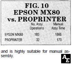 |
Conclusion In analyzing the Epson MX80 printer,care was taken to start with the same level of subassemblies as those used for the final assembly of the Proprinter. Thus the tractor, head drive, gear train and motor subassemblies match almost identical ones in the Proprinter. Comparison of the two product analyses, therefore, is valid as shown in the table, Fig. 10. It is felt that the Proprinter represents an outstanding design achievement and is highly suitable for manual assembly. |
The Server/Workstation installation
This kind of installation is typically used with a floating license of DFMA®, and is usually performed by a network administrator.
In this installation the DFMA software is installed on a server. A special setup program is run on the local workstation to complete the installation. When the software is started from the workstation, the program is loaded from the server, but temp and data files are saved on the workstation. We call this a server/workstation installation. However it is still a desktop application, and there is no dynamic writing to the server’s database. BDI recommends that DFMA applications not be run directly off the server by multiple users, to avoid data and installation corruption.
This server/workstation installation has some advantages:
7. When the license file is present, and you have rebooted the workstation if required, you can start the DFMA software.