


DYNAFORM: Die System Analysis Software
 |
Complete Die System Simulation Solution DYNAFORM is the complete die system simulation solution. DYNAFORM allows the organization to entirely bypass soft tooling, reducing overall tryout time, lowering costs, increasing productivity and providing complete confidence in die system design. It also allows evaluation of alternative and unconventional designs and materials for an optimal solution. The most cost-effective and accurate solution available, DYNAFORM is the clear choice among progressive organizations seeking to streamline the die analysis system. |
A Solid Infrastructure
DYNAFORM offers NURBS based CAD surfaces capability. This allows DYNAFORM’s mesh-based technology to maintain full parametric associativity throughout the entire simulation process. LS-DYNA , the most powerful solver in its class, is the engine within DYNAFORM. Offering tremendous calculation power to support difficult modeling and simulation challenges within a die system, these powerful processing and solving technologies enable DYNAFORM to meet the needs of users today and those in the future.
The Most Accurate & Cost-Effective Solution
The clear price/performance leader in the industry, DYNAFORM offers pin-point accuracy in every detail and is the key reason die designers all over the world have turned to DYNAFORM for the most precise analysis possible.
SOLVER: LS-DYNA™
The powerful dual-solver is the engine that powers the efficient processing environment of DYNAFORM, making it a complete simulation solution package. LS-DYNA uniquely offers both explicit & implicit solutions that can be seamlessly switched to correctly simulate the physics of virtually all engineering concerns of a die system including formability, springback, springback compensation, trimming, and flanging.
LS-DYNA™ is a trademark of Livermore Software Technology Corporation.
 FS-Formability-Simulation
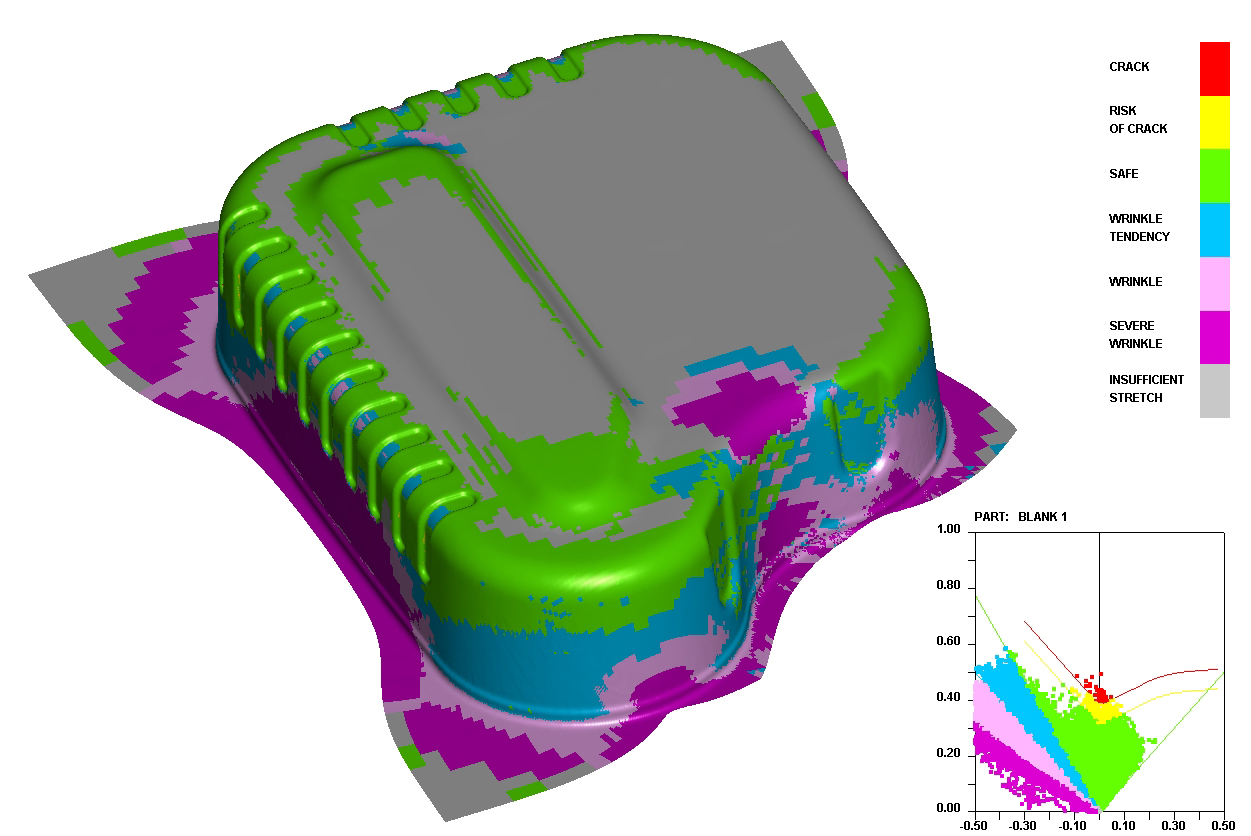 |
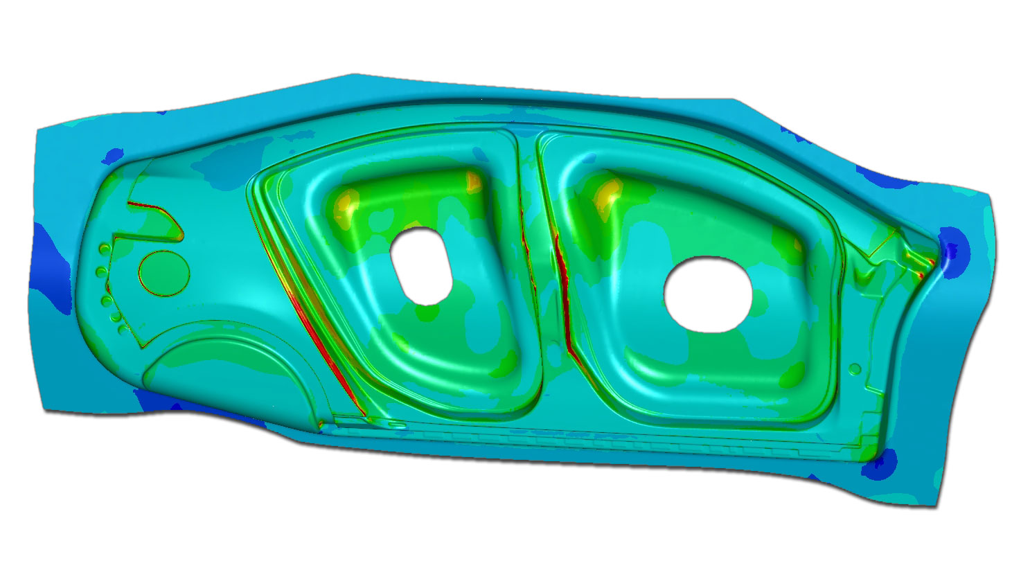
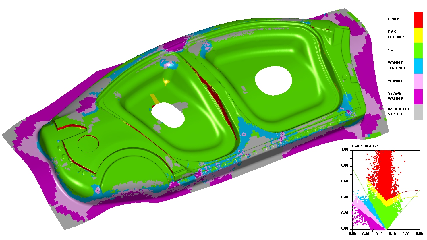
The Formability Simulation module uses LS-DYNA for accurate physics modeling, efficient calculation and in-depth simulation of the formability based on the die face design. The FLD (forming limit diagram), thinning map, wrinkling, material draw-in, circular grid, light strip and skid mark results identify weaknesses of the die face design. |
MSTEP & QuickSetup
In this module, a one-step solution using MSTEP is included to perform a quick evaluation of part formability. FS includes a QuickSetup for standard single-stage draw die and springback simulations.
Autosetup and Multiple-Stage Simulations
AutoSetup is available for complicated multiple-stage forming setups for all formability applications of various die systems. The AutoSetup interface visually guides the user through the setup process. All travel curves are automatically generated and multiple-stations can be setup seamlessly.
Hydroforming Capabilities
FS can support tube bending, tube hydroforming and sheet hydroforming.
Springback & Springback Compensation Process (SCP)
Using the DYNAFORM SCP, the user can determine and simulate the amount of springback compensation; simply define the selected tool to be compensated in SCP.
Special Forming Processes
FS can support stretch forming, thermal forming, roll forming and super plastic forming for specialized manufacturing processes.
Material Library
To maintain accuracy, the bundled material library contains a large selection of standard material types and users can also customize the library to meet specific needs such as:
• Gravity Load
• Draw Die
- Crash Form
- Inverted Draw (Single Action)
- Toggle Draw (Double Action)
• Trimming
• Flanging
• Re-strike
• Springback and Springback Compensation
• Tube Bending & Hydroforming
DFE-Die-Face-Engineer
Based on the product design of a panel, the DFE module offers capabilities of both CAD surface and CAE meshing tools. DFE Interactively generates binder surfaces, addendum profiles/surfaces, PO Lines and layout drawbeads with full associativity between FEA mesh and surfaces. A preliminary die face is created for further formability studies with an iterative process until die face validation is achieved.
Automated Tools
Using automated tools in both CAD surface and CAE mesh environments, DFE generates binder surfaces, addendum profiles/surfaces, PO line and layout drawbeads.
NURBS Surface Based Infrastructure
Compatible with all major CAD codes, high quality CAD surfaces are produced throughout the DFE module.
Automated
Automated tipping, reverse trimming, undercut/draw depth calculation, filleting and unflanging functions minimize the work required to design the die from the part geometry. Automated and flexible tools, such as morphing capability, are provided for binder surface and addendum profile generation, as well as fine adjustment.
Binder and Addendum Surface Generation
Based on part geometry, various CAD surface generation tools are provided to create, edit and morph the CAD surfaces to generate desirable binder surfaces. The advanced addendum generator creates a series of profiles based on draw depths and the shape of the part between the binder and the die cavity. The profiles are then meshed and surfaced to create a complete addendum for forming. Profiles can be edited using interactive functions or by adjusting the shape of the PO line.
Parametrical Definition
Addendum profiles and geometry drawbeads are parametrically defined. Quick adjustments are then possible by editing parameters.
Associativity
Since all surfaces and profiles are parametrically defined; the binder surface, addendum profiles/surfaces and PO Line are also fully associated. Therefore, modification of one entity can be extended to the other entities due to the associativity characteristics. This practice is implemented throughout the DFE module to fine-tune the addendum geometry.
Geometry Drawbeads (Available in DFE & FS)
Based on various benchmarks and extensive research, it has been determined that the geometry of the drawbeads have a great deal of influence on the accuracy of the springback results. Within DFE, the commonly used drawbead geometry can be parametrically generated and interchanged with the analytical (line) drawbead. This capability can be customized for various drawbead designs/applications.
BSE-Blank-Size-Engineer
The BSE module is a complete solution for accurate blank size estimation, nesting to maximize material utilization, piece price and scrap calculation. BSE is based on a one-step algorithm for rapid calculation. Potential forming failure due to excessive blank thinning is detected through an inverse method. BSE also creates a forming limit diagram (FLD) map for feasibility review.
 |
Beginning with the 3-D part geometry, BSE can quickly unfold the flanges and flatten the geometry to produce a blank outline for blank size estimation along with piece price and scrap calculation. Product feasibility and cost analysis can be thoroughly evaluated using BSE.
|
Nesting
The BSE module provides for 1-up, 2-up and multiple blank nesting. The material usage and fall off is calculated along with piece price. Minimum required blanking tonnage is estimated. Nesting optimization can be performed to calculate the best material utilization.
Cost Estimation Report
Automatically generate reports for cost estimation and quotation of the part material. Report output includes detailed descriptions of overall blank size, nesting configuration, pitch, coil width, material utilization, number of coils required to meet annual volume and total piece price for materials.
Feasibility Study using MSTEP
MSTEP is a one-step code which can be used for quick formability of a part. Binder, addendum and drawbeads can be simulated with pressure pads, binder and drawbead force.
Trimline Development with MSTEP
MSTEP will quickly and easily develop the trimline throughout multiple stations.
DSA-Die-System-Analysis
DSA offers an LS-DYNA based FEA solution to analyze die system operations including scrap shedding/removal, die structural integrity and sheet metal transferring/handling. Further development will include trimming, flanging and hemming operations.
 |
The Finite Element Analysis approach to die system design is an efficient way to predict and resolve many stamping related concerns within the die production line. Die System Analysis (DSA) simulations streamline die system design through the analysis of scrap shedding/removal, structural integrity and sheet metal transferring/handling. DSA's process guidance approach allows engineers to use simple graphic interfaces to execute complicated preparation and simulation processes. |
Scrap Shedding & Removal (SHR)
The number one cause of stamping line shutdown is the failure of scrap to exit the workstation. This problem can be predicted and corrected in the trim die design stage to avoid troubleshooting in the stamping plant. SHR streamlines model generation for scrap, trim dies, chutes and trim steel. Trimming operations and shedding simulations can be easily setup in the scrap shedding graphic interface.
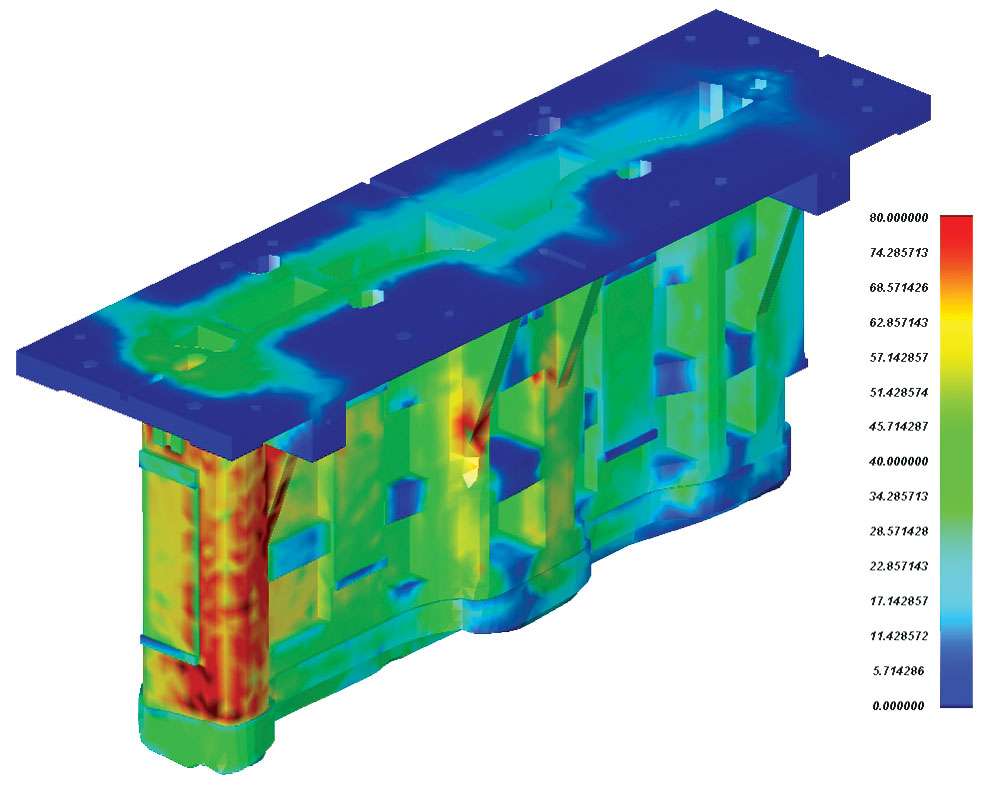
Die Structural Integrity (DSI)
DSI simulates operational loads to analyze the design integrity of the die. DSI can generate FEA models of the die structure, define operational/stamping loads and evaluate the die structure strength and durability by using implicit and explicit solutions.
Sheet Metal Transferring & Handling (SMTH)
SMTH simulates the transfer of metal as it progresses through the manufacturing process. It simulates the transfer of the work-piece to the initial die station, movement between stations, pick-up of the finished part and placement on the shipping rack. Part deformation generated in the simulation is used to predict interference between the work-piece and tools. The stress/strain results can be used to prevent damage during transportation, as well as loading and unloading operations.
G.S. Die & Design Inc.
Forming a Reputation for Excellence Using Dynaform
|
G.S. Die & Design Inc. was established in 1981, and since then has been committed to the business of Design & Manufacturing of Quality Automotive, and other Metal Stamping Dies. G.S. Die is dedicated to the continuous employment of new and advanced technology, allowing them to provide customers with high quality and competitively priced tooling. Three years ago G.S. Die went in |
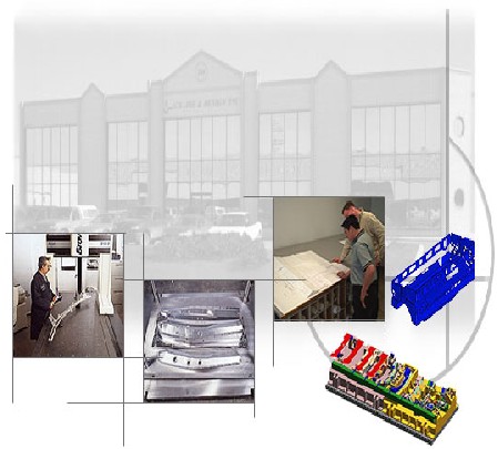 |
| As the automotive industry makes advances in vehicle construction techniques, new material specifications are often introduced in order to satisfy safety, weight, & rigidity concerns. Because of this, G.S. Die have recently found themselves in a position where completed diesrequire modification in order to perform successfully with new material types. To determine what changes are necessary, G.S. Die depends on Dynaform which gives them the freedom to easily simulate, and assess tool performance on different materials. With the data collected through these simulations, G.S. Die is able to quickly make modifications to their designs, and produce revised tooling suitable for new materials in the shortest possible time. |
 “As parts become more complex and the industry adopts new High Strength Materials, we must be able to run simulations to assure the die will produce the part continuously and accurately” -Tom Cacic, Manager of G.S. Die. |
 Explosive Productivity Gains “We simulate the first concept during the preliminary design stage. Once the first forming station is successful, we then move on to the second forming station and so on.”- Tom Cacic, G.S. Die. |
Established in 1981, G.S. Die employs over 85 engineers and toolmakers, and produces an average of 35 dies each year. Located in Mississauga, Ontario, G.S. Die pride themselves in keeping current with cutting edge software solutions, and the best in machine tool technology. It has always been G.S. Die’s goal to build dies bigger, better and faster, and with the implementation of Dynaform, that goal has become much easier to achieve. “You must stay current with software in order to stay cost effective. If the competition is using new software solutions like Dynaform to assist in building dies better and faster,then we have to adopt it as well." - Tom Cacic Manager of G.S.Die |
|
 “Dynaform allows us to meet shorter delivery timelines by designing the die right the first time.”–Tom Cacic, Manager of G.S. Die. |
Dynaform’s implementation at G.S. Die has been so successful, that the company recently added a second seat in order to keep up with new projects. By diligently applying Dynaform F.E.A.techniques through every stage of tool development, G.S. Die is able to move confidently through each new project, equipped with the foreknowledge that their dies will perform as intended the first time. |
|
 |
THE DIGITAL PRESS : TRYOUT BEFORE TOOLING DYNAFORM drastically reduces the risk and costs associated with the die design and development cycle by predicting formability problems before tooling takes place. Flawed or marginal die designs that would cost innumerable hours of labor, press time and material to repair and correct are evaluated on the computer at a fraction of the cost. By determining splitting, wrinkling, thinning, and springback effects that would occur during the stamping process before tooling is cut, timing concerns are eliminated while customer confidence and design confidence improve. DYNAFORM is a proven, cost-effective way to improve and insure your bottom-line. |
|
| ETA Software Inc. Contact Information |
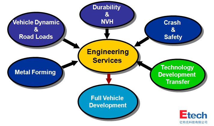
Engineering Services Overview: